DESCRIPTION
Install the UUC
Lightweight Flywheel and UUC Stage 3 Full Ceramic Clutch.
Either can be done seperately using this same DIY. This is the
13# full anodized aluminum flywheel from UUC along with their
new SPRUNG-HUB ceramic 4-puck clutch disc for the 6-speed
transmission. The 5-speed and 6-speed are totally different
transmissions and the parts are not interchangable.
PARTS NEEDED
1 - UUC Motorwerks 13# Lightweight
Flywheel
(UUC MOTORWERKS Coming Soon part#)
1 - UUC
Motorwerks Full Ceramic Clutch & Pressure
Plate
(UUC MOTORWERKS Coming Soon part#)
TOOLS NEEDED
A vehicle lift
Transmission
jacks
16mm, 14mm, 11mm, 10mm Wrenches/Sockets
T25, T35,
T50, and T60 Torx sockets
Socket Wrench
Long LONG socket
extension (~36")
Loctite (preferably the red type)
INSTALLATION
The use of a vehicle lift is almost
mandatory here. While possible with a floor jack and very tall
stands, it is just not simple, nor safe. Raise the vehicle on
a lift. I apologize in advance for the lack of detail, we were
working very fast to get this installation done and at times
the tech got a head of me. I will give as much information as
possible.
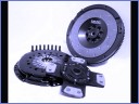
You can see a studio photo of the clutch and flywheel in
Photo SET. Let's begin.
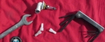
1. Remove the plastic undertray beneath the engine.
There are three (3) x Push Rivets and seven (7) x
phillips-head capture screws (Photo A is from my 2001 330i,
there is one more push rivet (blue circles) and one more screw
(red circles) on my 2004 330i).
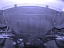
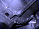
2. Remove the four (4) x 16mm transmission brace
bolts and the two (2) x 16mm bolts on the rubber support and
then remove brace (Photo B - Brace removed in photo).
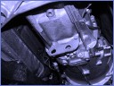
3. Remove the six (6) x 16mm bolts (Photo C) for the
metal reinforcment plate and remove the reinforcment plate
(Photo D).
4. Remove the exhaust system (refer to my UUC TSE3
DIY for this step).
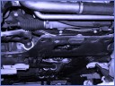
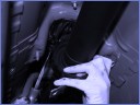
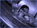
5. Use a 10mm socket to remove nuts for the heat
shield above the driveshaft and remove shield (Photo E).
6. Disconnect the reverse light switch harness
located in the passenger rear side of the transmission.
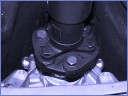
7. Remove the 16mm bolts on the guibo and pull the
driveshaft back from the transmission (Photo F - Red Circles).
The driveline will have some play in it, this allows the
driveline to move and expand. Do not pull the driveline apart.
8. Remove the 13mm nuts on the center driveline
bearing, pry it from the body (Photo G), and move the driveine
to the side and support it from falling. I used a piece of
bailing wire to secure it to the lift.
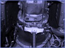
9. Use a transmission jack to support the weight of
the transmission (Photo H).
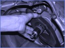
10. Remove the clip on the base of the shifter lever
and disconnect the linkage (Photo I). Save this clip and the
washers to reuse.
11. Remove the two (2) bolts from the clutch slave
cylinder and remove it from the transmission. You can leave
the fluid supply hose connected.
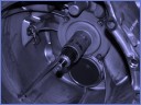
12. Remove the 10mm bolt from the bracket on the
passenger side of bell housing (Photo J). This clip holds the
reverse light harness.
13. Remove the T35 and T40 Torx bolts from around
the transmission bell housing (Photo K). Be ready to support
transmission.
14. Depending on the vehicle, you may have to remove
the starter or raise the front of the engine to access these
Torx bolt. We did both and also used about a 30" socket
extension. We used another transmission jack and a piece of
2x4 under the A/C compressor to tilt the engine back a bit. I
did *NOT* have to disconnect any other parts or remove
anything, including the supercharger intercooler piping,
microfilter housing, etc.
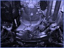
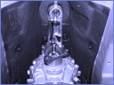
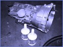
15. Pull the transmission straight back and down to
remove. Get help with this, it is not incredibly heavy, just
awkward.
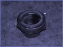
16. If you are replacing the pilot bearing (Photo
L), this is the input shaft it resides on (Photo M), replace
it with the new one. The tabs fit on the bumps in front of the
black throwout lever (Photo N).
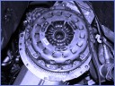
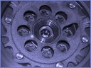
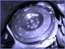
17. This is the factory self-adjusting pressure
plate (the evil S.A.C.) (Photo O). Remove the six (6) x 6mm
bolts from the pressure plate (Photo P)and remove the pressure
plate. The factory sprung-hub clutch disc should come with it.
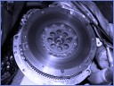
18. This is the factory dual-mass flywheel (Photo
Q). Remove the eight (8) x T50 Torx bolts from the flywheel
(Photo R) and remove flywheel. The stock flywheel is very
heavy (approximately 26lbs).
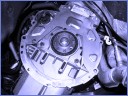
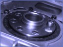
19. This is the rear main seal and flywheel mounting
face (Photo S). Take notice of the small alignment dowel
(Photo T - red circle). The pilot hole is larger and only one
hole has the dowel. Align the new lightweight flywheel's
larger hole on this dowel and fit into place (Photo U).
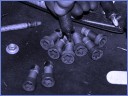
20. Loctite NEW flywheel bolts (Photo V), then
fasten flywheel in place tight. Tighten in a star pattern same
as you would a tire.
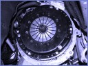
21. Using a clutch alignment tool through the new
pressure plate and clutch disc, install pressure plate to
flywheel (Photo W) and fasten in place with new suppled bolts.
22. Remove alignment tool. Clutch disc should be
perfectly centered in pressure plate. This allows easier
installation of the transmission.
23. I took this moment to change the fluid in the
transmission to Redline D4 ATF (Photo X). It is a high-quality
transmission fluid which has proven to reduce lightweight
flywheel chatter. Use a 14mm hex wrench to remove the lower
drain bolt. Drain fluid. Replace drain and remove 14mm fill
bolt. Add fluid and replace fill bolt. Once transmission is
installed, crack the install bolt a bit and drain off excess
fluid.
24. Installation is the simply the reverse of these
steps.
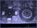
That's it. This is the new clutch and old clutch discs side
by side (Photo Y). Both flywheels and clutches require a
break-in when replaced. The friction surfaces need time to
build up a layer to work effectively. Take about 500 miles of
normal driving with LOTS of shifting to get them broken in. No
hard launches, shifts, or dragging the clutch during break-in.